The first big project

MAGNA

Background

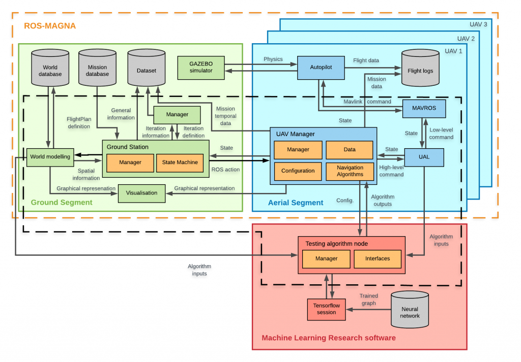
MAGNA was conceived to solve a problem I found when decided to practise ML applied to drones: there was no easy framework to alleviate all work required to prepare a set of simulated cooperative missions, direct testing algorithm integration and easy to modify agent behaviors and environment shapes.

Since that moment, the idea was expanding to accommodate features such as Tensorflow integration or the requirements of the GRVC projects that used MAGNA. Hence, the work done is a hybrid between my Master Thesis and my research work at GRVC. Part of the results of MAGNA were published. Explicative videos here.

GitHub code source

Focus of the project

Diverse civil applications require the cooperation of multiple unmanned air vehicles (multi-UAS) i.e. air traffic management, inspection or search and rescue. A common architecture is required as a useful testing tool for the development of UAS advanced.

MAGNA is a general framework for the definition and management of cooperative multi-UAS missions.

Main features

  • Fully integrated on ROS (Robot Operative System) standard for robotics development.
  • Modular components (nodes) communicated by topics, services and actions.
  • Any external algorithm is easy to be integrated obtaining all information and control as required.
  • Use of state machines built on SMACH that control the behaviour of the different UAS from the specification of the multi-UAS mission.
  • Rviz and SMACH viewer are used to visualized all data generated during the mission.
  • Virtual world generation tool to manage the spatial information of the environment and visualize the geometrical objects.
  • Transparent to the type of autopilot on-board.
  • Supports the coexistence of software-in-the-loop, hardware-in-the-loop and real UAS cooperating in the same arena thanks to UAL.
  • The standard way to introduce the different parameters of the mission is via JavaScript Object Notation (JSON) files or on the top frontend script.

Overall framework

The main differentiation is between Ground Segment, running on the computers on land, and Aerial Segment, embedded into the computer on-board the aerial vehicles.

Every node is governed by a parent component and influenced by the network of other diverse, adjacent ones.

Ground Segment

  • The master node is the front-end where the main features, such as the name of the world and mission, are defined. It remains active from the beginning of the collection of missions to be performed.
  • The Ground Station node is composed of two parts: central component manages communications and provides functions to implement different behaviours. The second one executes the state machine of the mission using the utilities offered by the central one.
  • Environment modelling tool also reads all shared spatial information and makes it available for all the components as part of the Ground Station.
  • If required on partly or fully simulated missions, GAZEBO simulator is also executed on this Segment.

Aerial segment

Each node, corresponding to one UAV, implements these components:

  • Manager. Maintains communications and retrieves and maps data from the GS and UAL. Generates a standard SM for UAV control coordinating the rest of onboard nodes. Generates objectives and specifications for each behavior and control of the performance.

  • Navigation Algorithm Interface. Decision making to select the attitude and velocity of the UAS depending on the current state, mission state, environment situation and target. Designed to be an interface to any new algorithm to be tested by providing access to all required information. Built-in modules: a simple greedy guidance algorithm, the Optimal Reciprocal Collision Avoidance (ORCA) algorithm and an interface to Tensorflow sessions.

  • Data. Retrieves information which is generated in the whole ROS network and makes it easily accessible to the UAV Manager.
  • Configuration. Homogenizes information that characterizes the UAV into common variables. That concerns to communications directions, the model or the implementation (SIL, HIL or real). Some of this information may be defined on the JSON of the mission.

Environment modelling tool

Creates the virtual 3D environment to monitor the execution of the mission. On the space segmentation, real or simulated objects and available positions of the space that can be accessed for different purposes called Free Space Poses (FSP) that can be associated in paths.

As for the mission, the top world component retrieves the definition from a JSON syntaxis and splits it into the definition of the child elements

Hierarchical structure:

  • Volume: gathered geometries for local positioning and standard features.
  • Geometry: model different restrictions of the scenario with a cube, a sphere, a cylinder or a prism. Standard functionalities for generic and others for specific shapes.
  • Pose arrays: groups of 3D poses gathered into arrays. Those would be extracted from features of the shape such as edges or direct coordinates. Used as auxiliaries to build other elements, as free space poses to reference paths or as obstacle positions.

Videos

These self-explicative videos show the potential of MAGNA for different situations.